Matrice 400 on Coastal Solar Farms: A Field Report
Matrice 400 on Coastal Solar Farms: A Field Report on Cooling, Vibration, and Link Discipline
META: Field-tested Matrice 400 guidance for coastal solar farm work, covering EMI handling, thermal inspection logic, airflow, structural vibration thinking, BVLOS link stability, and payload workflow decisions.
By Dr. Lisa Wang, Specialist
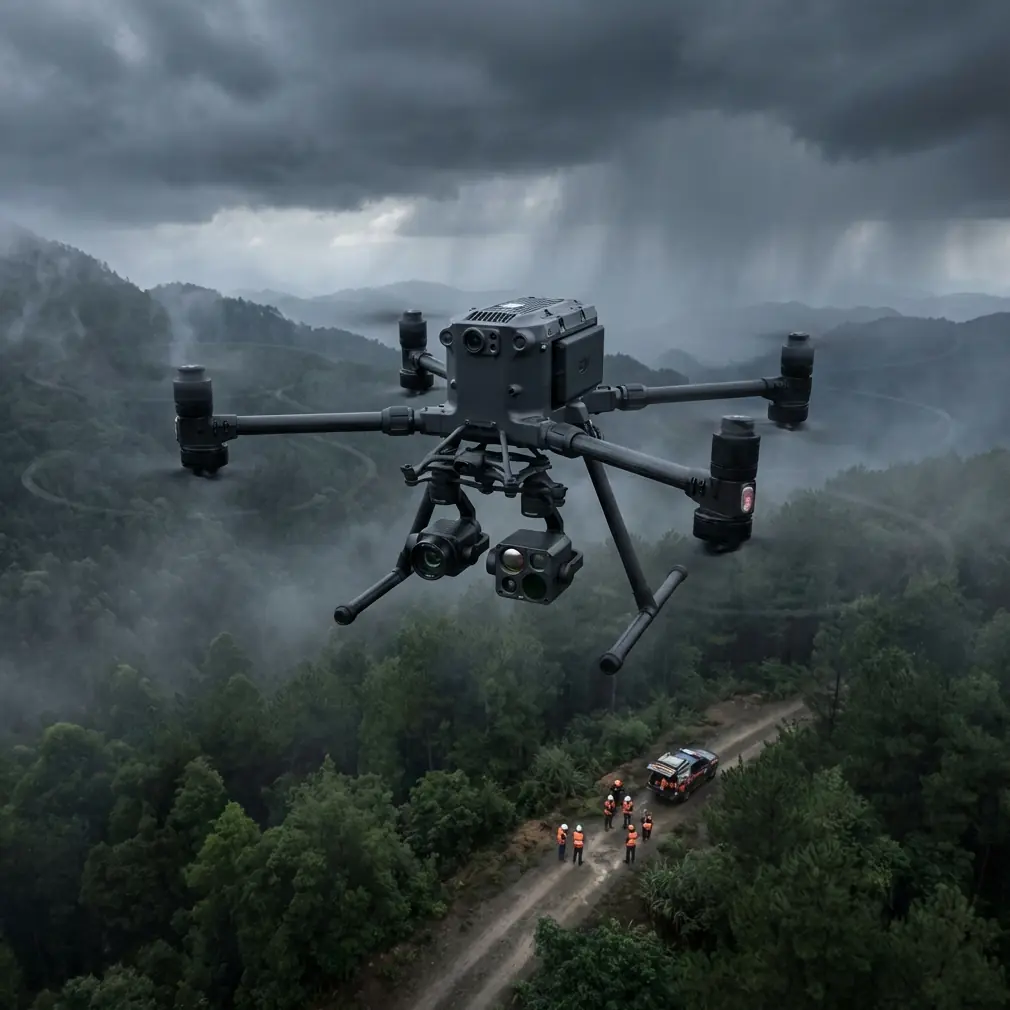
Coastal solar sites look clean on a project brief. In the field, they are messy in ways that matter to aircraft performance.
Salt air creeps into connectors. Wind rolls across panel rows and service roads with little warning. Large inverter blocks, transmission hardware, perimeter fencing, and utility equipment create pockets of electromagnetic interference that can turn an otherwise routine mapping or thermal mission into a troubleshooting exercise. When operators ask me what separates a smooth Matrice 400 deployment from a frustrating one, my answer is rarely “fly slower” or “buy more batteries.” It is usually about systems thinking.
That is why an old aircraft design lesson still translates surprisingly well to modern UAV work.
One of the reference materials behind this article comes from a Chinese aircraft design handbook section on landing gear dynamic testing and validation. It discusses how engineers do not guess at structural response; they build dynamic simulators around measured modal behavior. The text specifically refers to the first two fuselage horizontal bending modes and the use of resonance test modal values to solve for equivalent simulated mass and stiffness. Another passage explains that when torsional vibration frequency approaches the shimmy frequency, while horizontal bending is far away, a pure torsional simulator should be used instead.
That may sound far removed from a Matrice 400 flying over PV arrays. It is not. The operational significance is direct: if you want reliable data capture and stable control around large industrial infrastructure, you cannot treat vibration, resonance, and oscillation as abstract engineering trivia. They are part of image quality, payload accuracy, and flight safety. On coastal solar farms, the source terms are different from a crewed aircraft landing gear test bench, but the discipline is the same. Measure what the structure is doing. Separate bending-like disturbances from torsional-like disturbances. Then tune the platform, payload mount, flight profile, and antenna orientation accordingly.
Why coastal solar work is harder than inland routine inspection
A solar farm near the coast combines three stressors.
First, the environment is thermally deceptive. Early morning modules may be cool and uniform, but by mid-day the thermal signature spreads across strings, combiner areas, and soiled sections in a way that can bury genuine anomalies if you choose the wrong inspection window. The Matrice 400’s value here is not just lift capacity or endurance. It is the ability to carry a thermal workflow and a photogrammetry workflow with enough consistency to compare datasets without re-fighting aircraft stability every flight.
Second, the link environment can be ugly. Grid-tied installations often place power conversion equipment and cabling in dense clusters. Add coastal communications infrastructure, and O3 transmission performance becomes less about headline range and more about how intelligently the crew manages line-of-sight, antenna geometry, and site-specific interference. I have seen crews blame the aircraft for downlink instability when the real issue was operator body position and poor antenna angle relative to the corridor being flown.
Third, corrosion and contamination are real operational variables. Salt and fine dust do not always stop a mission immediately. They create gradual degradation: hotter electronics, stickier latches, dirtier vents, and more maintenance drift between flights.
A practical lesson from aircraft cooling design
The second reference document is nominally about aircraft structural design, but it contains a principle every Matrice 400 team working in coastal energy infrastructure should understand. It notes that for cooling engine accessories and certain components inside an engine bay, designers add dedicated ventilation features such as disc-type valves or ram-air inlets. It also emphasizes sealing: all system holes on the forward frame should be sealed, the rear end of the intake should use a shaped sealing ring, and all access openings should use in-place vulcanized sealing pads to reduce leakage and preserve cooling airflow effectiveness.
This is not a suggestion to modify the Matrice 400 with improvised ducting. Do not do that. The significance is procedural. Cooling only works when airflow goes where it is intended, and sealing only works when openings stay clean and intact. On a coastal solar project, crews often focus on battery state, RTK status, and route planning while ignoring the simple things that govern thermal reliability: vent cleanliness, payload bay sealing surfaces, access panel condition, and whether salt residue is beginning to compromise fit and airflow paths.
The handbook includes one very concrete dimensional detail: a frame width of 1200 mm, height of 600 mm, and depth of 250 mm in the structural discussion. For UAV operators, the exact frame is irrelevant, but the design mindset is valuable. Airframe compartments are geometric systems, not just empty spaces. Space allocation, airflow path, and sealing strategy determine whether heat leaves efficiently or lingers around critical electronics. On the Matrice 400, this translates into preflight inspection discipline. If a site is humid, salty, and hot, assume cooling margin is already under pressure. That affects how aggressively you schedule back-to-back sorties, how long you leave the aircraft baking on a vehicle tailgate, and how you rotate hot-swap batteries.
Hot-swap batteries are a productivity tool, not an excuse to rush
On paper, hot-swap batteries simplify field operations. In reality, they also tempt crews into compressing every turnaround.
At coastal solar farms, my preference is to use hot-swap capability for continuity of operation while building in a short inspection rhythm every cycle. That rhythm is simple: visual check of vents and latches, wipe-down of exposed surfaces, confirmation of payload seating, and a quick scan of motor arms and landing gear interfaces for contamination. The old aircraft cooling reference makes the case indirectly: leakage, poor sealing, and compromised airflow quietly erode system performance before any obvious failure appears.
If your team is flying thermal in the late morning and photogrammetry in the afternoon, battery handling also changes your data quality. Overheated packs do not just raise reliability concerns. They can alter your confidence in repeatability, especially when the route passes near EMI-heavy equipment and you need a predictable power response during hover checks or crosswind turns.
Handling electromagnetic interference with antenna adjustment
This is where many otherwise competent teams give away performance.
When flying the Matrice 400 in a coastal solar environment, EMI issues often show up near substations, inverter pads, and fenced utility junctions. The instinctive response is usually to climb, retreat, or blame the site. Sometimes that is correct. Often the faster fix is antenna discipline.
O3 transmission is robust, but it still depends on geometry. In the field, I brief crews to avoid “pointing the tips” at the aircraft. The broadside of the antenna pattern matters. If the aircraft transitions from a wide-area map leg to a low oblique inspection pass along inverter rows, the pilot or visual observer should reorient body position and controller angle to keep the strongest antenna relationship with the aircraft’s actual path, not its last known position. On coastal sites, where equipment yards can create localized interference pockets, a 15- to 30-degree change in operator stance can be more useful than a blanket route redesign.
I also recommend testing one short calibration leg before the full mission. Fly a controlled outbound segment near, but not directly above, the suspected interference source. Watch signal behavior, control latency, and video stability. If anomalies appear, adjust antenna orientation and repeat the leg from a slightly offset track. This gives you a practical interference map tied to the site, not a theoretical one.
That same discipline supports BVLOS planning where regulations and approvals permit. BVLOS is not simply a longer VLOS mission. It demands confidence in link behavior under worst-case geometry, not best-case conditions. A site with variable EMI requires stronger route validation, disciplined antenna management, and careful redundancy assumptions. AES-256 matters for data security; it does not solve signal blockage, bad orientation, or multipath issues.
Vibration thinking improves data quality
The first reference’s discussion of first- and second-order bending modes and torsional response has another takeaway for Matrice 400 operators: not all blur or payload instability comes from the same source.
If your orthomosaic shows directional softness on crosswind legs, you may be seeing a flight profile issue that resembles a bending-dominant disturbance: repeated airframe flex response, gimbal correction saturation, or speed and wind mismatch. If thermal imagery degrades mostly during yaw transitions around inverter stations, a torsional-like disturbance may be the better mental model: the aircraft and payload system are reacting to rotational inputs and local gust structure, not just linear buffeting.
That distinction matters because the fixes differ.
For bending-like issues:
- reduce speed on the affected leg,
- increase overlap in photogrammetry,
- recheck payload mounting rigidity,
- and avoid abrupt altitude changes over thermal plumes rising from equipment.
For torsional-like issues:
- smooth yaw rates,
- widen turn radii,
- avoid stopping directly in rotor-disturbed corners between structures,
- and confirm gimbal tuning is appropriate for the payload mass and mission style.
The handbook passage on using resonance test modal values to derive equivalent mass and stiffness parameters may sound academic, but it points toward a useful operating habit: diagnose disturbances by behavior, not by guesswork. Review logs, compare image artifacts by leg direction, and correlate them with site wind channels and aircraft attitude changes. That is how you turn a difficult site into a repeatable one.
Thermal and photogrammetry should not be flown as separate philosophies
On solar farms, teams often split into two camps. The thermal crew cares about emissivity, temperature spread, and anomaly detection. The mapping crew cares about GCP placement, overlap, and reconstruction fidelity. The Matrice 400 works best when those camps think together.
Thermal data without strong geospatial discipline is hard to operationalize at scale. Photogrammetry without thermal context can miss the maintenance priority hiding in plain sight. Coastal sites raise the stakes because corrosion, salt contamination, drainage behavior, and heat loading can create subtle performance differences across physically similar blocks.
My preferred workflow is to treat thermal and visible mapping as one site intelligence cycle. Establish GCPs where needed for your required absolute accuracy, capture visible data with enough overlap to support clean reconstruction, and align the thermal mission timing to the electrical and environmental conditions you actually want to diagnose. If the sea breeze ramps up every afternoon, do not force your highest-precision model capture into the noisiest air of the day just because the battery cart is ready.
Security, logistics, and the human factor
Solar operators increasingly care about how data moves, who holds it, and what leaves the site. AES-256 is relevant here because infrastructure owners are no longer satisfied with “the files are on a hard drive somewhere.” The aircraft is part of a broader information chain. Mission planning, onboard capture, transmission, and post-processing all need to match the client’s operational sensitivity.
The human factor still decides most outcomes, though. Crews who do well at coastal solar sites tend to have boring habits in the best sense. They document antenna positions that worked. They note which inverter row caused signal dips. They track battery temperature trends, not just remaining percentage. They inspect seals and ports because they understand cooling and contamination are linked. They use the Matrice 400 as a measurement platform, not just a flying camera.
If your team is building a repeatable workflow for coastal solar delivery or inspection, it helps to compare notes with operators who have already solved the same site-specific problems. If you want to discuss EMI handling, payload selection, or field setup details for a similar project, you can message our technical team here: https://wa.me/85255379740
What this means for Matrice 400 deployments right now
The strongest lesson from the source materials is not about copying crewed aircraft design methods onto a drone. It is about respecting the same engineering logic.
The first source shows that dynamic behavior must be characterized, separated, and modeled. The second shows that cooling effectiveness depends on airflow design and sealing integrity, not wishful thinking. Put those together, and you get a practical operating doctrine for the Matrice 400 on coastal solar farms:
Understand disturbance modes instead of treating all instability the same.
Manage link quality with deliberate antenna adjustment in EMI-heavy zones.
Protect thermal reliability through inspection of vents, seals, and turnaround practices.
Use hot-swap speed intelligently, not blindly.
Integrate thermal and photogrammetry as one decision system.
That is how the aircraft stops being a spec sheet and starts becoming a dependable field tool.
Ready for your own Matrice 400? Contact our team for expert consultation.