How I’d Plan a Windy Coastline Inspection with Matrice 400
How I’d Plan a Windy Coastline Inspection with Matrice 400
META: A field-focused Matrice 400 coastline inspection article covering windy conditions, installation discipline, grounding logic, interface control, thermal workflows, and why design coordination matters in real operations.
Windy coastline work has a way of exposing weak thinking.
Salt mist gets into every connector. Gust fronts arrive before the forecast says they should. Light angles shift, waves throw back glare, and a clean visual line on a cliff face can disappear in minutes. If you are planning a coastline inspection with Matrice 400, the aircraft matters, but the deeper story is the system around it: payload integration, cable discipline, grounding, interface control, data assurance, and the ability to keep operating when conditions stop being polite.
That is where the reference material becomes unexpectedly useful.
At first glance, the source documents come from traditional aircraft design practice rather than a drone field manual. Yet the principles map directly to a Matrice 400 deployment, especially for infrastructure and shoreline inspection. One document stresses that system coordination drawings should be produced at a unified scale, with datum lines, major installation dimensions, hole positions, motion paths, and even limit positions clearly marked. Another emphasizes that installation rules, interface boundaries, and clearance distances must be jointly defined so loads, systems, and maintenance access all make sense together. For a windy coastal mission, those are not bureaucratic details. They are what separates a reliable sortie from a preventable abort.
The real problem with coastline inspection is not just wind
Most operators think the challenge begins with flight stability. That is only part of it.
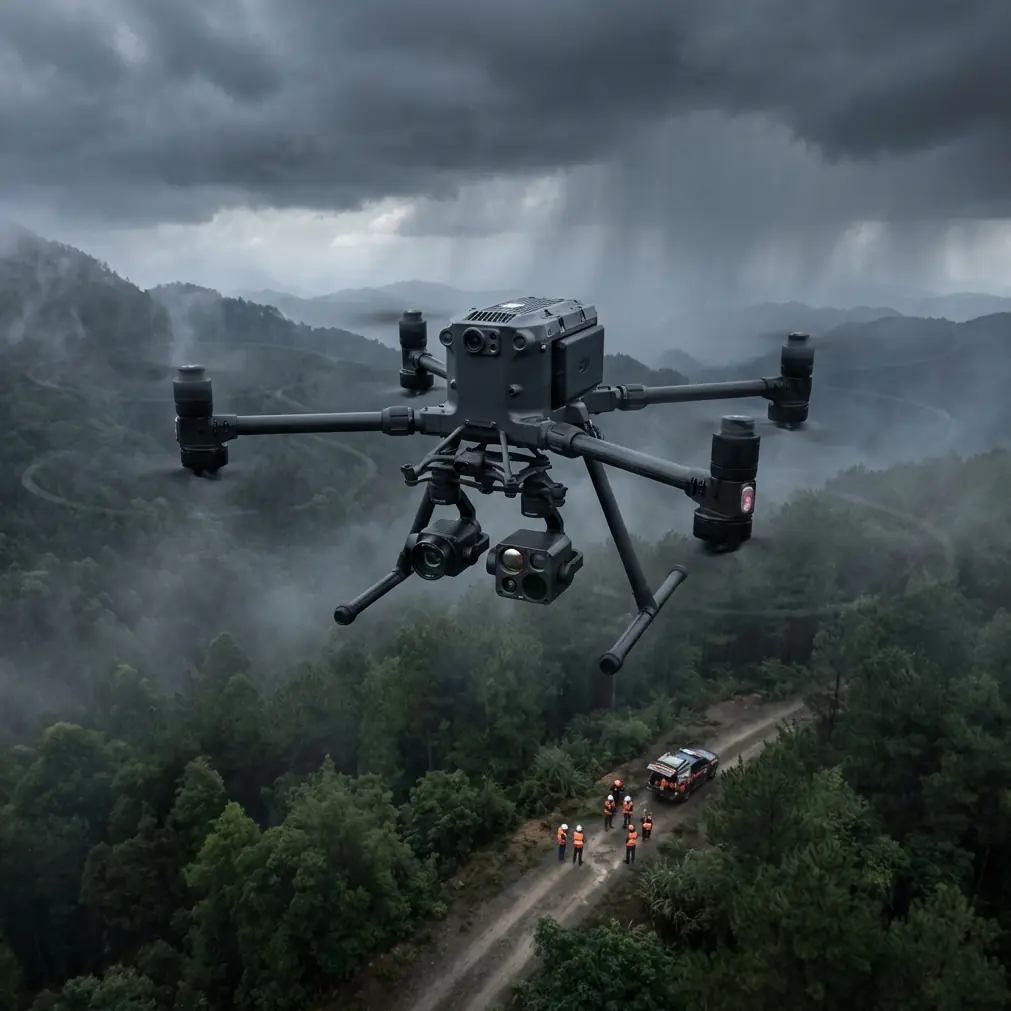
Coastline inspection usually combines several sensing tasks in one window: visible imaging for erosion and asset condition, thermal signature checks for moisture ingress or void detection in coastal structures, and photogrammetry for measurable terrain or revetment change. Add the usual field realities—launching from uneven ground, limited recovery zones, corrosion risk, intermittent comms, and pressure to finish before the tide or weather turns—and the mission becomes a systems problem.
That matters for Matrice 400 because readers looking at this platform are often thinking beyond a single camera on a simple route. They are planning a configured aircraft with multiple mission roles, secure data handling, long links using O3 transmission, perhaps future BVLOS workflows where regulation allows, and battery strategies that reduce turnaround time. Once you move into that category, integration discipline becomes central.
The aircraft may be advanced, but poor mission architecture still causes failure.
What aircraft design manuals can teach a Matrice 400 team
One of the most practical ideas in the first reference is the requirement that equipment, harnesses, ducts, rods, cables, and mounts be coordinated in relation to each other, and that movement trajectories and extreme positions be shown explicitly. In manned aviation, this prevents interference between moving and fixed components. In a drone context, the same logic applies to payload gimbal sweep, landing gear clearances, antenna placement, battery exchange access, and the routing of any external accessories or specialized sensors.
For a coastline inspection build on Matrice 400, this becomes operationally significant in two ways.
First, it protects sensor usability. If your thermal payload has an obstructed field of view at certain gimbal angles, or if an added accessory creates unexpected reflections or airflow disturbance, your data set degrades quietly. You may only notice back in processing, when the thermal mosaic has unusable sectors or the photogrammetry set lacks overlap in the exact corridor you needed.
Second, it protects aircraft behavior in rough air. Coastal gusts can induce larger attitude corrections and more aggressive gimbal compensation. If the installed equipment and its movement envelope were never treated as a coordinated system, edge-case interference shows up when the weather gets ugly, not in the office.
The old manual’s insistence on marking motion trajectories with centerlines and limit positions with distinct notation may sound very analog, but the lesson is current: if the component can move, document its full envelope before the aircraft sees the field.
A mid-flight weather change is where process earns its keep
Let me make this concrete.
Imagine a Matrice 400 team inspecting sea walls, drainage outlets, and rock armor along an exposed section of coast. The first leg goes smoothly. O3 transmission holds the link cleanly despite the open terrain. The crew is collecting overlapping visible imagery for photogrammetry and intermittent thermal passes where runoff paths are suspected. GCPs were placed earlier where safe access allowed, giving the mapping team a stronger reference framework instead of relying only on onboard positioning.
Then conditions change.
A marine layer shifts inland. Wind speed rises unevenly along the cliff edge. Sun breaks through in patches, changing thermal contrast on concrete and wet stone. The aircraft can still fly, but now the mission is under stress from three directions at once: flight stability, data consistency, and time pressure.
This is exactly the sort of moment where good pre-coordination shows up.
If payload interfaces were defined properly before deployment, the crew already knows which sensor transitions are worth making and which are not. If access space around components and hot-swap batteries was considered in the setup plan, turnaround stays fast instead of becoming a fiddly deck-side operation while weather worsens. If the mounting and cable arrangement was thought through like a proper installation system—not an improvised add-on—the aircraft remains predictable under gust loading and repeated repositioning.
That second reference document is highly relevant here. It notes that installation design should define measurement requirements, distances to surrounding structure, interfaces between systems, and maintenance space, with all parties agreeing on the criteria. The manned-aircraft example discusses engine installations and even distance from the ground, but the transferable principle is obvious: mission hardware only works well when interfaces and clearances are agreed before operations begin.
For Matrice 400 coastline work, that means asking practical questions early:
- Can the selected payload complete both thermal and visual objectives in one sortie?
- Does the mounting configuration preserve all required gimbal movement?
- Are battery swaps, lens cleaning, and storage media access possible without disturbing alignment?
- Is the crew managing a single integrated system, or a stack of loosely connected parts?
Wind does not create these weaknesses. It reveals them.
Grounding and interference: an underrated issue near the sea
The first document also includes a detail many drone operators ignore until they encounter unexplained noise: grounding and bonding.
It states that aircraft electrical systems may use the airframe as ground and warns that grounding points must be selected carefully to prevent interference, citing a general grounding resistance range of 100 to 200. You do not need to copy fixed-wing architecture directly onto a UAV to appreciate the point. The operational meaning is simpler: electrical returns, bonding decisions, and component grounding quality affect system noise and reliability.
Why does this matter during coastal inspection with Matrice 400?
Because coastline work often puts sensors in harsh electromagnetic and environmental conditions at the same time. You may be operating near marine communications infrastructure, power assets, radar-adjacent zones, or simply in damp, salt-laden air that punishes connectors and exposed interfaces. Thermal payloads, video links, GNSS performance, and onboard recording all depend on clean system behavior. If the aircraft ecosystem includes external modules, third-party accessories, mobile ground equipment, or improvised power arrangements, interference risk rises.
This is where secure and stable digital workflows matter too. O3 transmission helps sustain the command-and-video chain. AES-256 matters when inspection data includes sensitive infrastructure imagery being relayed or stored in regulated environments. But encryption and transmission specs do not replace electrical discipline. They sit on top of it.
A drone can have excellent comms architecture on paper and still perform poorly if the integrated field setup is electrically noisy.
Why records matter more than memory
Another strong idea from the source is the use of coordination record sheets and signoff by the relevant specialists, with multiple copies retained by each party. That sounds formal, but it solves a field problem every serious UAV team knows: tribal knowledge is fragile.
If your Matrice 400 coastline workflow depends on one technician remembering which payload cable path avoids gimbal pinch, or one pilot knowing the exact battery sequence that preserves tempo, you do not have a robust operation. You have a habit.
Record discipline turns habit into repeatability.
For a drone team, the equivalent is not necessarily a classic aerospace signoff form. It may be a configuration sheet, preflight integration checklist, payload alignment log, maintenance note, or mission profile template. The point is the same as in the aircraft manual: once installation positions, interfaces, and coordination decisions are settled, capture them clearly so they are not lost, misremembered, or re-litigated on the shoreline.
This becomes especially valuable when weather shifts mid-flight and the team has to make decisions fast. A documented workflow tells the crew what has already been validated. That shortens deliberation and reduces improvisation at the worst possible time.
If your team is refining that kind of operational setup, it may help to message a UAV integration specialist directly to sanity-check payload layout, workflow sequencing, and handoff between flight and data teams.
The maintenance-space lesson applies directly to hot-swap tempo
The second source document stresses that installation design must account not only for the system itself but also the space needed to maintain it. That one sentence has real value for Matrice 400 users.
In coastline operations, maintenance space is mission space.
If the aircraft supports hot-swap batteries, that feature only pays off when the surrounding process has been engineered around it. Can the crew stage replacement packs without contamination from blowing sand or salt spray? Can batteries be exchanged without shifting the aircraft awkwardly on unstable ground? Can payloads remain mounted without blocking safe handling? Can the team keep turnaround short enough to preserve light conditions for photogrammetry consistency?
Many operators blame the aircraft when they lose efficiency. Often the problem is that no one designed the support choreography.
A proper Matrice 400 coastline setup treats the drone, payload, batteries, landing surface, cases, and operator positions as one coordinated zone. The old aircraft-design language of structure, equipment, openings, routes, and acceptance review may sound far removed from drones. In practice, it is exactly the mindset that makes advanced UAV operations feel calm.
Noise, airflow, and the coastal sensor stack
The propulsion-system source also mentions acoustic treatment and validation through high- and low-speed wind-tunnel testing, along with interface rules around installation geometry. Obviously, Matrice 400 users are not running wind-tunnel programs. But the underlying principle remains useful: airflow and installation geometry affect system performance, and they should be validated, not assumed.
For coastal inspection, this matters with thermal and visual sensors alike.
Crosswinds and rotor wash can influence image stability, especially around vertical surfaces. Moist air and temperature gradients can distort thermal interpretation. Sensor placement and aircraft attitude strategy affect whether you get a clean thermal signature or a messy composite of reflections, wet surfaces, and transient heating. In photogrammetry, changing wind and surf glare can weaken tie points, making GCPs even more valuable in exposed sections where consistency is hard to maintain.
A Matrice 400 mission plan should therefore be built around data quality thresholds, not just flight completion. It is better to adapt the route and preserve usable output than to stubbornly finish a line with degraded imagery that cannot support engineering decisions.
The bigger takeaway for Matrice 400 buyers and operators
The most useful thing in these references is not a hardware specification. It is the discipline behind complex airborne systems.
One document says coordination is only accepted as a basis for detailed design after review by quality, technical, and chief design authority. Another stresses jointly defined installation standards, interfaces, and space claims. Together, they point to a mature truth: successful aerial platforms are not assembled by wishful thinking. They are integrated through explicit decisions, recorded clearly, and checked before operations depend on them.
That is the right lens for evaluating Matrice 400 for windy coastline inspection.
Yes, you should care about payload capability, thermal performance, transmission integrity, encryption, battery workflow, and future BVLOS relevance. But if you stop there, you miss what actually drives field success. The winning team is usually the one that treats the aircraft as an installed system with known interfaces, controlled clearances, grounded electrical logic, documented configurations, and fast maintenance choreography.
When the weather changes halfway through the mission, that discipline shows up as confidence. The crew adjusts altitude bands, keeps overlap where it matters, protects the thermal task from bad assumptions, swaps batteries cleanly, and lands with data that can actually be used.
That is the difference between flying a drone and operating an aerial inspection system.
Ready for your own Matrice 400? Contact our team for expert consultation.