Matrice 400 for Windy Construction Mapping: Control Logic
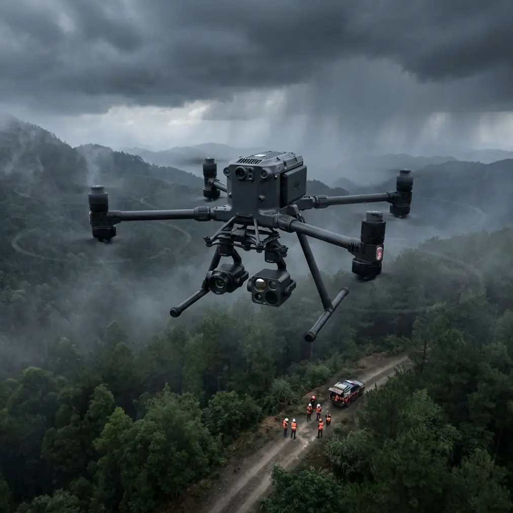
Matrice 400 for Windy Construction Mapping: Control Logic, Antenna Setup, and What Actually Protects Data Quality
META: A field-focused Matrice 400 tutorial for mapping construction sites in wind, covering control stability, antenna positioning, photogrammetry reliability, and operational planning.
By Dr. Lisa Wang, Specialist
Mapping a construction site in steady wind is rarely a camera problem first. It becomes a control problem, then a data problem, and only after that a deliverables problem.
That order matters with the Matrice 400.
If your aircraft cannot hold the line cleanly, your overlap suffers. If overlap suffers, your photogrammetry output starts to drift at the edges, vertical structures get messy, and your ground control point checks begin showing the kind of errors nobody wants to explain in a progress meeting. A windy mission punishes every weak link in the chain: flight control stability, operator monitoring, transmission discipline, and the way the payload data is collected across repeated passes.
What is useful here is that the reference material behind this discussion is not marketing copy. It comes from aircraft control-system design logic and flight-load design practice. Those ideas were written for larger aircraft, but the engineering lesson translates well to a professional UAV platform like the Matrice 400: stable guidance, protected operating limits, and control-system resilience are not abstract features. They are what make mapping in wind practical instead of hopeful.
Why wind mapping starts with flight-control behavior
One detail from the flight-control reference stands out: the flight control computer system provides pitch and roll signals to the flight director display so the pilot can monitor or manually follow guidance even when servos are not engaged. Operationally, that is a big deal.
For a Matrice 400 crew mapping a construction site, the equivalent lesson is simple: do not treat automation as a black box. Even when the mission route is built well, the pilot should be actively reading aircraft behavior, not just waiting for waypoint completion. Wind introduces moment-to-moment attitude corrections. If those corrections become large, repetitive, or asymmetrical on parallel legs, your final map may still process, but the geometry quality can degrade long before the aircraft reaches any obvious alert condition.
The source also notes that integrated control functions should keep the aircraft from exceeding the maximum operating speed, and that dynamic parameters such as pitch angle and normal acceleration should be limited to preserve comfort and structural integrity. For a drone mission, the significance is not passenger comfort, of course. The relevance is image consistency and mechanical protection. Aggressive pitch transients in headwind-to-tailwind transitions can create uneven groundspeed, changing photo spacing right where the site needs clean uniform coverage. Limiting those abrupt dynamics protects both the aircraft and the survey result.
In practice, when flying Matrice 400 over a windy construction site, this means you should build missions that the control system can execute smoothly rather than theatrically. Slightly slower mapping speed, more conservative turns, and a route aligned with the dominant wind often outperform a “faster” plan that forces large corrections every leg.
The hidden enemy in site mapping: directional inconsistency
Construction sites are difficult because they are not flat agricultural blocks. You have cranes, partially enclosed concrete frames, rebar forests, HVAC equipment, temporary fencing, steel staging, dust, and heat wash coming off machinery. Wind interacts with all of that.
This creates two forms of inconsistency:
Aircraft-path inconsistency
The aircraft drifts or corrects unevenly along the route.Scene inconsistency
Dust plumes, moving machinery, reflective surfaces, and changing shadow edges alter tie-point reliability.
The Matrice 400 is being considered here for mapping, so the real objective is not simply to keep it airborne. The objective is to produce a stable image set for photogrammetry while preserving enough margin for safe site operations.
That is where control-system thinking from the reference becomes useful. The text describes how functions can be distributed between a basic flight control computer system and a flight management computer system, with both together providing basic autopilot capability. For UAV operators, the operational parallel is that the mission result depends on both layers working together: guidance logic and route-management logic. A perfect camera grid does not rescue poor stabilization. Likewise, excellent stabilization does not rescue a mission plan built with unrealistic lane spacing or bad wind alignment.
So when you set up a windy-site mission on the Matrice 400, think in systems:
- Aircraft control quality
- Transmission reliability
- Camera trigger consistency
- Overlap margin
- GCP layout and check-point distribution
- Reflight repeatability
If one is weak, the others carry more load.
Antenna positioning advice for maximum range on a construction site
The brief asked for practical antenna advice, and this is where many crews quietly lose performance.
On a construction site, range is often not limited by distance alone. It is limited by geometry, obstructions, and multipath reflection. Steel frame buildings, container stacks, tower cranes, and temporary site offices create RF clutter. Even with strong O3 transmission performance and encrypted links such as AES-256, your physical setup still matters.
Here is the field rule I give crews using Matrice 400-class systems:
Point the flat face of the controller antennas toward the aircraft’s working area, not the antenna tips.
That sounds basic, but many operators still aim the tips like old radio whips. On a large mapping grid, especially when the aircraft is offset across a broad construction footprint, this mistake can reduce link quality faster than wind itself.
A few specifics:
- Stand where the aircraft will have the longest clear line of sight during the central part of the mission, not just at takeoff.
- Keep your body, truck roof, and metal fencing out of the immediate antenna plane.
- If the site has a steel frame rising on one side, position yourself so the bulk of the mission remains away from that reflective wall.
- Maintain antenna orientation as the aircraft transitions from outbound to inbound lanes. Tiny posture changes can matter when signal paths are already compromised by structures.
- Avoid standing directly beside generators, site communications trailers, or dense machinery clusters if another safe launch point is available.
If you are planning repeated windy flights over a complex site and want a quick pre-mission workflow for controller orientation and line-of-sight setup, send the crew request here: field setup checklist for antenna alignment.
The value of good antenna discipline is not only preserving command and video. It also reduces operator stress. That matters because a calm crew catches mapping issues earlier.
Wind, overlap, and why GCPs become more valuable
In benign conditions, some teams get casual about overlap margins because the platform is stable and the site is open. Wind removes that luxury.
Any drift correction changes how the camera path sits over the target. On construction sites with vertical elements, that can create reconstruction weakness along slab edges, retaining walls, facade lines, or trench boundaries. When wind is strong enough to demand visible correction, you should think less about “minimum overlap” and more about “error absorption.”
That is where GCPs earn their keep.
Ground control points do not fix poor flying, but they do constrain the final model and expose where the image block has become uneven. In a windy Matrice 400 mission, distribute GCPs so they test the whole site, not just the perimeter. Include elevation variation, the far corners, and at least a few points near structurally dense areas where tie points are more likely to struggle.
A practical pattern for construction mapping is:
- perimeter control
- interior control
- separate checkpoints not used in adjustment
- visibility planned around active work zones and safe access
If the mission also uses thermal signature capture alongside RGB, remember that thermal data is especially sensitive to timing and environmental variation. Wind can cool some surfaces and alter the contrast patterns you expect to see. That matters if your mapping objective includes roof moisture analysis, façade heat leakage review, or equipment heat tracking on a live site. Thermal is useful, but in wind it should be collected intentionally, not as a casual add-on to an RGB survey.
What aircraft load logic teaches drone crews
The second reference document is about loads, strength, and stiffness. At first glance that may seem far removed from UAV mapping. It is not.
One of the more revealing details is that in spoiler control systems, designers must consider jam scenarios and design mechanical paths to withstand fault-overriding loads. Another detail is even more interesting: the horizontal stabilizer trim system is normally electrically controlled, but emergency trim is manual, and the screw-jack assembly and its support can function as a structural support point, so worst-case tensile and compressive loading must be considered.
Why should a Matrice 400 operator care?
Because these details illustrate how serious aircraft designers think about abnormal conditions. They do not assume the control path behaves perfectly. They assume something may bind, overload, or require fallback logic.
Translate that mindset into drone operations and you get better field decisions:
- Do not launch in wind just because the platform can technically hover.
- Inspect gimbals, mounts, landing gear, and payload fastening with the same seriousness you give battery status.
- Treat repeated high-wind braking and turning as cumulative stress, especially on long mapping days.
- Plan conservative abort criteria before takeoff.
The reference also includes a very specific figure: 125% of the maximum aerodynamic hinge load, or the hydraulic actuator’s maximum output pressure, as a design basis for spoiler-related loading. That number matters not because your Matrice 400 uses the same architecture, but because it reflects the engineering principle of margin. A professional UAV crew should also build margin into mission design. If the wind forecast suggests the aircraft can complete the grid only at the edge of acceptable correction behavior, the right move is often to shorten the grid, split the mission, or fly in a better window.
Margin protects data quality as much as hardware.
Battery strategy in wind: think continuity, not just endurance
Hot-swap batteries are one of those practical features that become more valuable on a live construction site than they look on a brochure.
Wind increases power demand. Repositioning for line of sight increases mission-management complexity. Site activity may force temporary holds. When all of that happens, efficient battery handling becomes part of your mapping quality plan. Hot-swap capability helps preserve sortie rhythm, which matters when you need consistent lighting, repeated geometry, or a narrow site-access window.
For Matrice 400 operators, this means:
- stage the next battery set before landing
- log wind trend changes between sorties
- compare image consistency if the mission is split across time
- keep relaunch intervals short when trying to preserve matching light and shadow conditions
A fractured mission is still workable. A fractured mission with changing wind direction, changing sun angle, and poor continuity notes is where reconstruction headaches begin.
BVLOS planning should not weaken survey discipline
Some readers will be evaluating Matrice 400 with BVLOS aspirations in mind. That can make sense for large corridor or infrastructure work, but construction mapping usually benefits from disciplined proximity and stronger visual oversight, especially in wind and around cranes or tall structures.
Even where BVLOS is operationally permitted, the survey logic remains the same: maintain line quality, preserve image geometry, and ensure the aircraft is not fighting the environment so hard that your data set becomes irregular. Transmission strength, encrypted links, route automation, and robust control are all helpful. None of them replace site-specific judgment.
A practical windy-site workflow for Matrice 400 crews
Here is the method I recommend when the goal is photogrammetry-grade site mapping:
1. Read the site before you read the map
Identify steel masses, crane swing zones, dust sources, exhaust plumes, and likely RF reflections.
2. Place the pilot station for the middle of the mission, not the launch photo
Optimize controller line of sight and antenna geometry for the longest working portion of the route.
3. Align flight lines with the wind when possible
This reduces repeated lateral correction and helps maintain more uniform track spacing.
4. Slow down enough to protect image spacing
A smooth route at lower speed often yields cleaner reconstruction than a fast route with constant correction.
5. Increase overlap margin
Wind is error pressure. Give your photogrammetry workflow more redundancy.
6. Use GCPs and checkpoints intentionally
Do not let the site perimeter be your only source of control.
7. Watch aircraft attitude, not just waypoint progress
The reference emphasis on pitch and roll guidance is a reminder: the operator should monitor flight behavior continuously.
8. Split missions before the aircraft is forced to fight
If wind is building, divide the site into manageable blocks.
9. Use hot-swap efficiency to preserve consistency
Fast, organized turnarounds reduce light-change and workflow drift.
10. Debrief every sortie
Note wind direction, strongest correction zones, link quality dips, and image anomalies while they are fresh.
The real standard for a “successful” Matrice 400 mapping flight
A successful mission is not one where the aircraft finishes the grid. That is a low bar.
A successful Matrice 400 construction mapping flight in wind is one where the aircraft remained within stable control behavior, the transmission link stayed clean because the crew understood antenna geometry, the imagery preserved photogrammetric integrity, and the control framework included enough margin to avoid forcing the platform into ugly corrections.
That is the deeper lesson hidden in the reference materials. Flight-control systems are built around guidance clarity, envelope protection, and integrated function sharing. Load design assumes faults, overrides, and worst-case forces. Bring that same engineering mindset to your Matrice 400 fieldwork, and windy construction mapping becomes much more predictable.
The best operators are not the ones who fly the toughest conditions for bragging rights. They are the ones who know when stability, signal geometry, and data quality are all aligned—and when they are not.
Ready for your own Matrice 400? Contact our team for expert consultation.