Mastering Power Line Monitoring in Low Light: A Beginner's Guide to the Matrice 400 RTK
Mastering Power Line Monitoring in Low Light: A Beginner's Guide to the Matrice 400 RTK
TL;DR
- The Matrice 400 RTK delivers 55 minutes of flight time and RTK positioning accuracy essential for safe, precise power line inspections during dawn, dusk, and overcast conditions
- Low-light operations require specific camera settings, flight planning adjustments, and thermal signature interpretation skills that differ significantly from daylight missions
- IP45 weather resistance and O3 Enterprise transmission ensure mission continuity even when conditions deteriorate unexpectedly
- Beginners can achieve professional-grade results by following systematic pre-flight protocols and understanding the unique challenges of infrastructure monitoring
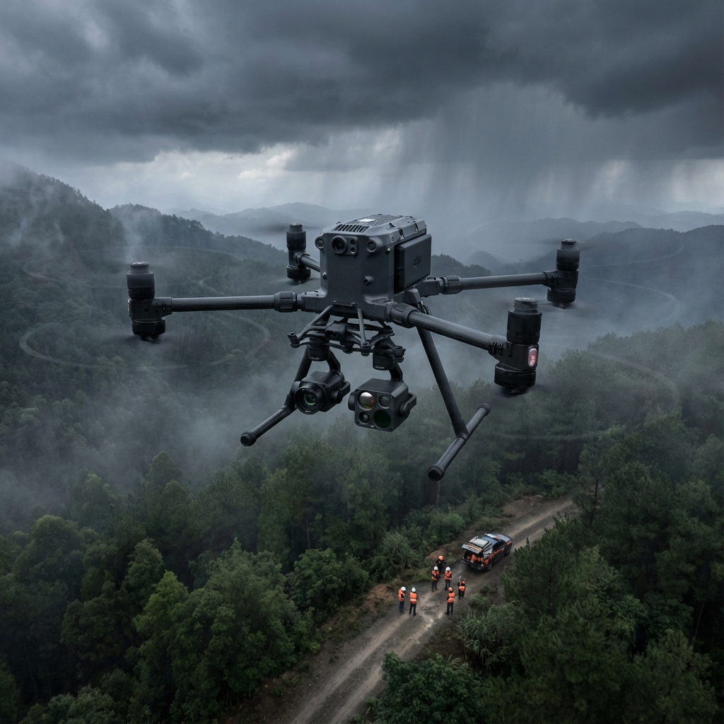
The call came at 4:47 AM. A regional utility company reported flickering service across three substations, and they needed aerial thermal analysis before the morning load surge. As I prepped the Matrice 400 RTK in near-darkness, I knew this mission would test everything I'd learned about low-light power line monitoring over fifteen years in photogrammetry.
What happened next—including an unexpected weather system that rolled in mid-flight—reinforced why proper preparation and reliable equipment make the difference between mission success and costly failure.
This guide walks you through every step of conducting power line inspections in challenging lighting conditions, from equipment setup to data processing.
Understanding Low-Light Power Line Monitoring Fundamentals
Power line infrastructure presents unique inspection challenges that intensify during low-light conditions. Thermal anomalies indicating potential failures—hot spots from loose connections, overloaded conductors, or failing insulators—actually become more visible when ambient temperatures drop during early morning or evening hours.
The temperature differential between a failing component and its surroundings creates a stronger thermal signature during these periods. This phenomenon makes dawn and dusk ideal windows for detecting problems invisible during midday operations.
Expert Insight: I've found that the optimal thermal contrast window occurs when ambient temperatures sit between 10-15°C below the expected component operating temperature. For standard distribution lines, this typically means scheduling flights 45-90 minutes before sunrise or 60-120 minutes after sunset.
The Matrice 400 RTK excels in these conditions for several critical reasons:
- RTK positioning maintains centimeter-level accuracy regardless of lighting conditions
- 2.7kg payload capacity accommodates professional thermal imaging systems
- AI payload integration enables real-time anomaly detection during flight
- Hot-swappable batteries allow extended operations without returning to base
Essential Pre-Flight Preparation for Low-Light Missions
Step 1: Site Assessment and Flight Planning
Before any low-light operation, conduct thorough reconnaissance during daylight hours. Document all obstacles, including:
- Guy wires and support cables
- Vegetation encroachment zones
- Communication towers and antenna arrays
- Terrain elevation changes along the corridor
Create your flight path using photogrammetry software that accounts for the specific corridor geometry. Power line monitoring requires flight paths that maintain consistent distance from conductors—typically 15-25 meters horizontal offset for distribution lines and 30-50 meters for transmission infrastructure.
Step 2: Configure RTK Base Station
The Matrice 400 RTK requires proper base station configuration for maximum positioning accuracy. During low-light operations, this precision becomes non-negotiable—you cannot visually confirm your distance from energized conductors with the same confidence as daylight flights.
Establish your base station with clear sky visibility and allow minimum 10 minutes for convergence before launching. The RTK system will achieve ±1cm horizontal and ±1.5cm vertical accuracy once fully converged.
Step 3: Thermal Sensor Calibration
Thermal imaging systems require specific calibration for low-light conditions:
- Perform flat-field correction (NUC) immediately before launch
- Set appropriate temperature range based on expected component temperatures
- Configure palette for maximum contrast in your specific scenario
- Verify focus using a known reference target
| Calibration Parameter | Daytime Setting | Low-Light Setting | Reason for Adjustment |
|---|---|---|---|
| Temperature Range | Wide (−20°C to 150°C) | Narrow (−10°C to 80°C) | Increased sensitivity to subtle anomalies |
| Gain Mode | Low | High | Compensates for reduced thermal contrast |
| NUC Interval | Every 10 minutes | Every 5 minutes | Temperature drift more significant |
| Focus Distance | Variable | Fixed at mission distance | Prevents hunting in low contrast scenes |
Executing the Low-Light Inspection Flight
Step 4: Launch and System Verification
Launch the Matrice 400 RTK and hover at 10 meters AGL for system verification. Confirm:
- RTK fix status showing "Fixed" (not "Float" or "Single")
- Thermal feed displaying clearly on your ground station
- O3 Enterprise transmission showing strong signal quality
- All obstacle avoidance sensors functioning
The O3 Enterprise transmission system maintains reliable video feed up to 20km in optimal conditions, though low-light operations rarely require such range. More critically, the system's AES-256 encryption protects your infrastructure data—essential when documenting utility vulnerabilities.
Step 5: Corridor Navigation and Data Capture
Begin your systematic corridor sweep using the pre-programmed flight path. The AI payload capabilities of the Matrice 400 RTK enable real-time thermal anomaly flagging, but I recommend capturing continuous footage for post-flight analysis rather than relying solely on automated detection.
Maintain consistent flight parameters:
- Ground speed: 3-5 m/s for thermal data quality
- Altitude: Constant relative to conductor height
- Gimbal angle: 45-60 degrees for optimal thermal perspective
- Overlap: 70% forward, 50% side for point cloud generation
Pro Tip: When monitoring three-phase systems, fly parallel to the corridor rather than perpendicular. This approach captures all three conductors simultaneously, allowing direct temperature comparison between phases—the fastest method for identifying load imbalances.
The Weather Challenge: When Conditions Change Mid-Mission
During that early morning mission I mentioned, everything changed at the 23-minute mark. A fog bank rolled in from the adjacent river valley—something the forecast hadn't predicted. Visibility dropped from clear to approximately 200 meters within minutes.
The Matrice 400 RTK handled this external challenge with remarkable composure. The IP45 rating meant moisture accumulation posed no threat to the aircraft systems. The RTK positioning continued providing centimeter-accurate location data despite the visual obscuration. Most critically, the O3 Enterprise transmission maintained solid connection to my ground station, allowing me to monitor the situation and make informed decisions.
I executed a controlled altitude increase to rise above the densest fog layer, completed the remaining corridor segment, and returned safely with complete thermal documentation. The utility company received their analysis report by 8 AM, identifying three connection points requiring immediate attention.
This experience reinforced a fundamental truth: external environmental challenges will occur. Your equipment must be the reliable constant that enables mission success regardless of what nature presents.
Post-Flight Data Processing for Power Line Analysis
Step 6: Thermal Data Review and Anomaly Classification
Transfer your captured data and begin systematic review. Thermal anomalies in power line infrastructure fall into several categories:
Critical (Immediate Action Required)
- Temperature differentials exceeding 30°C above ambient
- Hot spots at connection points or splice locations
- Thermal patterns indicating internal conductor damage
Moderate (Schedule Maintenance)
- Temperature differentials between 15-30°C
- Insulator thermal anomalies
- Vegetation contact thermal signatures
Monitor (Document for Trending)
- Temperature differentials below 15°C
- Consistent patterns across similar components
- Seasonal baseline variations
Step 7: GCP Integration and Georeferencing
For clients requiring precise location data—and most utility companies do—integrate Ground Control Points into your photogrammetry workflow. The RTK data from the Matrice 400 RTK provides excellent positioning, but GCP validation ensures your deliverables meet survey-grade standards.
Place GCPs at minimum 4 locations along the corridor, with additional points at direction changes or areas of particular interest. This enables generation of accurate point cloud data and digital twin models that utility companies increasingly require for asset management systems.
Step 8: Report Generation and Deliverable Preparation
Professional power line inspection reports should include:
- Executive summary with critical findings
- Georeferenced thermal imagery with anomaly annotations
- Temperature measurement data for each identified issue
- Recommended action priorities
- Flight metadata including environmental conditions
Common Pitfalls in Low-Light Power Line Monitoring
Even experienced operators make mistakes during challenging low-light missions. Avoid these frequent errors:
Rushing Pre-Flight Calibration Thermal sensors require adequate warm-up time—typically 15-20 minutes for professional-grade systems. Launching before full thermal stabilization produces inconsistent data that complicates analysis.
Ignoring Wind Patterns at Dawn/Dusk Thermal boundary layers create unpredictable wind conditions during transition periods. What feels calm at ground level may present significant gusts at conductor height. Always check conditions at multiple altitudes before committing to your flight path.
Overlooking Battery Temperature Cold batteries deliver reduced capacity. The 55-minute flight time specification assumes batteries at optimal operating temperature. Pre-warm batteries to 20-25°C before low-light missions in cool conditions.
Insufficient Overlap for Point Cloud Generation Reduced lighting affects visual camera performance, which impacts photogrammetry processing. Increase overlap percentages by 10-15% compared to daylight operations to ensure adequate feature matching.
Failing to Document Environmental Conditions Your thermal data interpretation depends heavily on ambient conditions. Record temperature, humidity, wind speed, and cloud cover at mission start and completion. This metadata proves essential for accurate anomaly assessment.
BVLOS Considerations for Extended Corridor Monitoring
As regulations evolve, Beyond Visual Line of Sight operations are becoming increasingly accessible for infrastructure monitoring. The Matrice 400 RTK platform supports BVLOS operations with appropriate waivers and operational protocols.
For beginners, focus on mastering visual line of sight operations before pursuing BVLOS authorization. The skills developed—systematic flight planning, real-time decision making, and data quality management—transfer directly to extended operations.
Contact our team for consultation on developing BVLOS operational capabilities for your power line monitoring program.
Building Your Low-Light Monitoring Expertise
Proficiency in low-light power line monitoring develops through deliberate practice. Start with shorter corridor segments during optimal conditions, then progressively challenge yourself with longer missions and more demanding lighting scenarios.
The Matrice 400 RTK provides a platform capable of growing with your skills. Its combination of RTK precision, extended flight time, and robust construction means the equipment won't limit your development—only your experience and training will.
Document every mission thoroughly. Review your thermal captures critically. Seek feedback from utility engineers on your deliverables. This iterative improvement process transforms beginners into trusted infrastructure monitoring specialists.
Frequently Asked Questions
What minimum lighting conditions does the Matrice 400 RTK require for safe power line monitoring?
The Matrice 400 RTK operates effectively in extremely low light conditions, including pre-dawn and post-sunset periods. The limiting factor is typically your visual camera performance for photogrammetry rather than aircraft operation. Thermal imaging actually performs optimally during these periods due to enhanced temperature differentials. For obstacle avoidance, the aircraft's sensor suite functions independently of ambient lighting, though operators should maintain heightened situational awareness when visual references diminish.
How do I maintain accurate positioning when flying near high-voltage transmission lines that may cause electromagnetic interference?
High-voltage infrastructure can create electromagnetic interference affecting GPS signals. The RTK positioning system on the Matrice 400 RTK mitigates this challenge through differential correction, which filters out common-mode errors including some EMI effects. Position your RTK base station minimum 100 meters from major transmission infrastructure, and monitor your fix status throughout the mission. If you observe degradation from "Fixed" to "Float" status, increase your offset distance from the conductors and allow the system to re-converge before continuing data capture.
What thermal sensor specifications should I prioritize for detecting early-stage power line component failures?
For effective power line thermal analysis, prioritize sensors with thermal sensitivity (NETD) below 50mK and minimum resolution of 640x512 pixels. The 2.7kg payload capacity of the Matrice 400 RTK accommodates professional radiometric thermal cameras meeting these specifications. Additionally, ensure your sensor provides calibrated temperature measurement rather than relative thermal imaging only—accurate temperature values are essential for classifying anomaly severity and prioritizing maintenance responses.
Dr. Lisa Wang specializes in photogrammetry applications for infrastructure monitoring, with particular expertise in thermal analysis methodologies for utility asset management.